


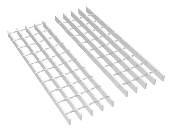


RG-1: Riveted grating with smooth surface.
Riveted grating is one of the steel grating products available with high load capacity, flexibility, alkali and acid resistance and anti-slip surface. It uses high-strength rivets to fuse the reticulated and bearing bars together and forms a solid joint. It can be constructed of carbon steel, stainless steel or aluminum. Additionally, it is available in both smooth and serrated surfaces. Riveted grating can be widely used as stair treads, walkways, floors, covers and bridge decking.
RG-1: Riveted grating with smooth surface.

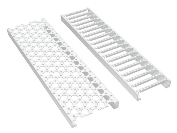
RG-2: Riveted grating with serrated surface.

RG-3: Riveted grating with serrated surface.
Specifications:

RG-4: Smooth surface

RG-5: Serrated surface

RG-6: coding rules

RG-7: 18-R-7

RG-8: 12-R-7

RG-9: 18-R-3.5

RG-10: 12-R-3.5
| Bearing Bar Size (inches) | Approx. Weight psf * | Maximum Pedestrian Span** | Load Types | Unsupported Span | |||||||||||
|---|---|---|---|---|---|---|---|---|---|---|---|---|---|---|---|
| 2'-0 | 2'-6 | 3'-0 | 3'-6 | 4'-0 | 4'-6 | 5'-0 | 5'-6 | 6'-0 | 6'-6 | 7'-0 | 8'-0 | ||||
| 3/4 × 3/16 | 7.8 | 4'-0" | U | 613 | 392 | 272 | 200 | 153 | 121 | 98 | All loads and deflections are theoretical and based upon the gross sections of the bearing bars, using a fiber stress of 18,000 psi. The values are not intended to be absolute since the actual load capacity will be affected by the slight variations in mill and manufacturing tolerances. Grating for spans to the left of the heavy line have a deflection ≤ 1/4" for uniform loads of 100 psf. |
||||
| D | 0.099 | 0.155 | 0.223 | 0.304 | 0.397 | 0.503 | 0.621 | ||||||||
| C | 613 | 490 | 409 | 350 | 306 | 272 | 245 | ||||||||
| D | 0.079 | 0.124 | 0.179 | 0.243 | 0.318 | 0.402 | 0.497 | ||||||||
| 1 × 1/8 | 7.6 | 4'-5" | U | 726 | 465 | 323 | 237 | 182 | 144 | 116 | |||||
| D | 0.074 | 0.116 | 0.168 | 0.228 | 0.298 | 0.377 | 0.466 | ||||||||
| C | 726 | 581 | 484 | 415 | 363 | 323 | 291 | ||||||||
| D | 0.06 | 0.093 | 0.134 | 0.182 | 0.238 | 0.302 | 0.372 | ||||||||
| 1 × 3/16 | 9.4 | 4'-11" | U | 1090 | 697 | 484 | 356 | 272 | 215 | 174 | 144 | U - uniform load in pounds/sq. ft. C - concentrated load in pounds/ft. of grating width D - deflection in inches |
|||
| D | 0.074 | 0.116 | 0.168 | 0.228 | 0.298 | 0.377 | 0.466 | 0.563 | |||||||
| C | 1090 | 872 | 726 | 623 | 545 | 484 | 436 | 396 | |||||||
| D | 0.06 | 0.093 | 0.134 | 0.182 | 0.238 | 0.302 | 0.372 | 0.451 | |||||||
| 1-1/4 × 1/8 | 8.7 | 5'-3" | U | 1135 | 726 | 504 | 371 | 284 | 224 | 182 | 150 | 126 | / | / | / |
| D | 0.06 | 0.093 | 0.134 | 0.182 | 0.238 | 0.302 | 0.372 | 0.451 | 0.536 | / | / | / | |||
| C | 1135 | 908 | 757 | 649 | 567 | 504 | 454 | 413 | 378 | / | / | / | |||
| D | 0.048 | 0.074 | 0.107 | 0.146 | 0.191 | 0.241 | 0.298 | 0.36 | 0.429 | / | / | / | |||
| 1-1/4 × 3/16 | 11 | 5'-10" | U | 1702 | 1090 | 757 | 556 | 426 | 336 | 272 | 225 | 189 | 161 | / | / |
| D | 0.06 | 0.093 | 0.134 | 0.182 | 0.238 | 0.302 | 0.372 | 0.451 | 0.536 | 0.629 | / | / | |||
| C | 1702 | 1362 | 1135 | 973 | 851 | 757 | 681 | 619 | 567 | 524 | / | / | |||
| D | 0.048 | 0.074 | 0.107 | 0.146 | 0.191 | 0.241 | 0.298 | 0.36 | 0.429 | 0.504 | / | / | |||
| 1-1/2 × 1/8 | 9.9 | 6'-0" | U | 1634 | 1046 | 726 | 534 | 409 | 323 | 262 | 216 | 182 | 155 | 133 | 102 |
| D | 0.05 | 0.078 | 0.112 | 0.152 | 0.199 | 0.251 | 0.31 | 0.376 | 0.447 | 0.524 | 0.608 | 0.794 | |||
| C | 1634 | 1307 | 1090 | 934 | 817 | 726 | 654 | 594 | 545 | 503 | 467 | 409 | |||
| D | 0.04 | 0.062 | 0.089 | 0.122 | 0.159 | 0.201 | 0.248 | 0.3 | 0.358 | 0.42 | 0.487 | 0.636 | |||
| 1-1/2 × 3/16 | 12.5 | 6'-8" | U | 2451 | 1569 | 1090 | 800 | 613 | 484 | 392 | 324 | 272 | 232 | 200 | 153 |
| D | 0.05 | 0.078 | 0.112 | 0.152 | 0.199 | 0.251 | 0.31 | 0.376 | 0.447 | 0.524 | 0.608 | 0.794 | |||
| C | 2451 | 1961 | 1634 | 1401 | 1226 | 1090 | 981 | 891 | 817 | 754 | 700 | 613 | |||
| D | 0.04 | 0.062 | 0.089 | 0.122 | 0.159 | 0.201 | 0.248 | 0.3 | 0.358 | 0.42 | 0.487 | 0.636 | |||
| 1-3/4 × 3/16 | 14.2 | 7'-6" | U | 3337 | 2135 | 1483 | 1090 | 834 | 659 | 534 | 441 | 371 | 316 | 272 | 209 |
| D | 0.043 | 0.067 | 0.096 | 0.13 | 0.17 | 0.215 | 0.266 | 0.322 | 0.383 | 0.45 | 0.521 | 0.681 | |||
| C | 3337 | 2669 | 2224 | 1907 | 1668 | 1483 | 1335 | 1213 | 1112 | 1027 | 953 | 834 | |||
| D | 0.034 | 0.053 | 0.077 | 0.104 | 0.136 | 0.172 | 0.213 | 0.257 | 0.306 | 0.36 | 0.417 | 0.545 | |||
| 2 × 3/16 | 16.8 | 8'-3" | U | 4358 | 2789 | 1937 | 1423 | 1090 | 861 | 697 | 576 | 484 | 413 | 356 | 272 |
| D | 0.037 | 0.058 | 0.084 | 0.114 | 0.149 | 0.189 | 0.233 | 0.282 | 0.335 | 0.393 | 0.456 | 0.596 | |||
| C | 4358 | 3486 | 2905 | 2490 | 2179 | 1937 | 1743 | 1585 | 1453 | 1341 | 1245 | 1090 | |||
| D | 0.03 | 0.047 | 0.067 | 0.091 | 0.119 | 0.151 | 0.186 | 0.225 | 0.268 | 0.315 | 0.365 | 0.477 | |||
| 2-1/4 × 3/16 | 18.3 | 9'-0" | U | 5515 | 3530 | 2451 | 1801 | 1379 | 1090 | 883 | 729 | 613 | 522 | 450 | 345 |
| D | 0.033 | 0.052 | 0.074 | 0.101 | 0.132 | 0.168 | 0.207 | 0.25 | 0.298 | 0.35 | 0.406 | 0.53 | |||
| C | 5515 | 4412 | 3677 | 3152 | 2758 | 2451 | 2206 | 2006 | 1839 | 1697 | 1576 | 1379 | |||
| D | 0.026 | 0.041 | 0.06 | 0.081 | 0.106 | 0.134 | 0.166 | 0.2 | 0.238 | 0.28 | 0.324 | 0.424 | |||
| 2-1/2 × 3/16 | 19.9 | 9'-9" | U | 6809 | 4358 | 3026 | 2223 | 1702 | 1345 | 1090 | 900 | 757 | 645 | 556 | 426 |
| D | 0.03 | 0.047 | 0.067 | 0.091 | 0.119 | 0.151 | 0.186 | 0.225 | 0.268 | 0.315 | 0.365 | 0.477 | |||
| C | 6809 | 5447 | 4540 | 3891 | 3405 | 3026 | 2724 | 2476 | 2270 | 2095 | 1946 | 1702 | |||
| D | 0.024 | 0.037 | 0.054 | 0.073 | 0.095 | 0.121 | 0.149 | 0.18 | 0.215 | 0.252 | 0.292 | 0.381 | |||
| * Weight per square foot based upon rivets spaced at 7" on center. Add .40 psf for 3-1/2" rivet centers. ** Maximum pedestrian load is defined as a 100# uniform load with deflection ≤ 1/4 inch. The 1/4" maximum deflection criteria is considered consistent with pedestrian comfort, but may be exceeded for other loading conditions at the discretion of the specifying authority. |
|||||||||||||||
| Bearing Bar Size (inches) | Approx. Weight psf * | Maximum Pedestrian Span** | Load Types | Unsupported Span | |||||||||||
|---|---|---|---|---|---|---|---|---|---|---|---|---|---|---|---|
| 2'-0 | 2'-6 | 3'-0 | 3'-6 | 4'-0 | 4'-6 | 5'-0 | 5'-6 | 6'-0 | 6'-6 | 7'-0 | 8'-0 | ||||
| 3/4 × 3/16 | 10.7 | 4'-4" | U | 858 | 549 | 381 | 280 | 215 | 170 | All loads and deflections are theoretical and based upon the gross sections of the bearing bars, using a fiber stress of 18,000 psi. The values are not intended to be absolute since the actual load capacity will be affected by the slight variations in mill and manufacturing tolerances. Grating for spans to the left of the heavy line have a deflection ≤ 1/4" for uniform loads of 100 psf. |
|||||
| D | 0.099 | 0.155 | 0.223 | 0.304 | 0.397 | 0.503 | |||||||||
| C | 858 | 686 | 572 | 490 | 429 | 381 | |||||||||
| D | 0.079 | 0.124 | 0.179 | 0.243 | 0.318 | 0.402 | |||||||||
| 1 × 3/16 | 12.8 | 5'-4" | U | 1525 | 976 | 678 | 498 | 381 | 301 | 244 | 202 | U - uniform load in pounds/sq. ft. C - concentrated load in pounds/ft. of grating width D - deflection in inches |
|||
| D | 0.074 | 0.116 | 0.168 | 0.228 | 0.298 | 0.377 | 0.466 | 0.563 | |||||||
| C | 1525 | 1220 | 1017 | 872 | 763 | 678 | 610 | 555 | |||||||
| D | 0.06 | 0.093 | 0.134 | 0.182 | 0.238 | 0.302 | 0.372 | 0.451 | |||||||
| 1-1/4 × 3/16 | 15 | 6'-4" | U | 2383 | 1525 | 1059 | 778 | 596 | 471 | 381 | 315 | 265 | / | / | / |
| D | 0.06 | 0.093 | 0.134 | 0.182 | 0.238 | 0.302 | 0.372 | 0.451 | 0.536 | / | / | / | |||
| C | 2383 | 1907 | 1589 | 1362 | 1192 | 1059 | 953 | 867 | 794 | / | / | / | |||
| D | 0.048 | 0.074 | 0.107 | 0.146 | 0.191 | 0.241 | 0.298 | 0.36 | 0.429 | / | / | / | |||
| 1-1/2 × 3/16 | 17.1 | 7'-3" | U | 3432 | 2196 | 1525 | 1121 | 858 | 678 | 549 | 454 | 381 | 325 | 280 | 215 |
| D | 0.05 | 0.078 | 0.112 | 0.152 | 0.199 | 0.251 | 0.31 | 0.376 | 0.447 | 0.524 | 0.608 | 0.794 | |||
| C | 3432 | 2745 | 2288 | 1961 | 1716 | 1525 | 1373 | 1248 | 1144 | 1056 | 981 | 858 | |||
| D | 0.04 | 0.062 | 0.089 | 0.122 | 0.159 | 0.201 | 0.248 | 0.3 | 0.358 | 0.42 | 0.487 | 0.636 | |||
| 1-3/4 × 3/16 | 19.4 | 8'-2" | U | 4671 | 2989 | 2076 | 1525 | 1168 | 923 | 747 | 618 | 519 | 442 | 381 | 292 |
| D | 0.043 | 0.067 | 0.096 | 0.13 | 0.17 | 0.215 | 0.266 | 0.322 | 0.383 | 0.45 | 0.521 | 0.681 | |||
| C | 4671 | 3737 | 3114 | 2669 | 2336 | 2076 | 1868 | 1699 | 1557 | 1437 | 1335 | 1168 | |||
| D | 0.034 | 0.053 | 0.077 | 0.104 | 0.136 | 0.172 | 0.213 | 0.257 | 0.306 | 0.36 | 0.417 | 0.545 | |||
| 2 × 3/16 | 22.9 | 9'-0" | U | 6101 | 3905 | 2712 | 1992 | 1525 | 1205 | 976 | 807 | 678 | 578 | 498 | 381 |
| D | 0.037 | 0.058 | 0.084 | 0.114 | 0.149 | 0.189 | 0.233 | 0.282 | 0.335 | 0.393 | 0.456 | 0.596 | |||
| C | 6101 | 4881 | 4067 | 3486 | 3050 | 2712 | 2440 | 2219 | 2034 | 1877 | 1743 | 1525 | |||
| D | 0.03 | 0.047 | 0.067 | 0.091 | 0.119 | 0.151 | 0.186 | 0.225 | 0.268 | 0.315 | 0.365 | 0.477 | |||
| 2-1/4 × 3/16 | 25 | 9'-10" | U | 7721 | 4942 | 3432 | 2521 | 1930 | 1525 | 1235 | 1021 | 858 | 731 | 630 | 483 |
| D | 0.033 | 0.052 | 0.074 | 0.101 | 0.132 | 0.168 | 0.207 | 0.25 | 0.298 | 0.35 | 0.406 | 0.53 | |||
| C | 7721 | 6177 | 5148 | 4412 | 3861 | 3432 | 3089 | 2808 | 2574 | 2376 | 2206 | 1930 | |||
| D | 0.026 | 0.041 | 0.06 | 0.081 | 0.106 | 0.134 | 0.166 | 0.2 | 0.238 | 0.28 | 0.324 | 0.424 | |||
| 2-1/2 × 3/16 | 27.2 | 10'-8" | U | 9533 | 6101 | 4237 | 3113 | 2383 | 1883 | 1525 | 1261 | 1059 | 903 | 778 | 596 |
| D | 0.03 | 0.047 | 0.067 | 0.091 | 0.119 | 0.151 | 0.186 | 0.225 | 0.268 | 0.315 | 0.365 | 0.477 | |||
| C | 9533 | 7626 | 6355 | 5447 | 4766 | 4237 | 3813 | 3466 | 3178 | 2933 | 2724 | 2383 | |||
| D | 0.024 | 0.037 | 0.054 | 0.073 | 0.095 | 0.121 | 0.149 | 0.18 | 0.215 | 0.252 | 0.292 | 0.381 | |||
| * Weight per square foot based upon rivets spaced at 7" on center. Add .40 psf for steel products with 3-1/2" rivet centers. ** Maximum pedestrian load is defined as a 100# uniform load with deflection ≤ 1/4 inch. The 1/4" maximum deflection criteria is considered consistent with pedestrian comfort, but may be exceeded for other loading conditions at the discretion of the specifying authority. |
|||||||||||||||
Features:
Applications of riveted grating:
Light Duty Riveted Grating:
Heavy Duty Riveted Grating:

RG-11: Riveted grating walkway.

RG-12: Riveted grating bridge decking.

RG-13: Riveted grating operating platform.